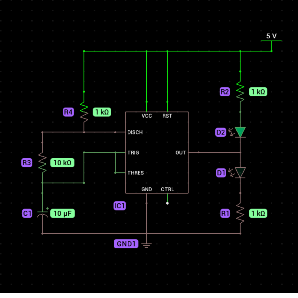
Alternating LED Flasher Circuit Using a 555 Timer
What It Does:
This simple circuit uses a 555 timer IC to alternately blink two LEDs on and off in a continuous cycle. This is achieved by configuring the 555 timer in astable mode, which generates a square wave output. The circuit is perfect for learning how the 555 timer operates and can also be used in visual signaling or as a fun DIY project for beginners.

Components Needed:
- 555 Timer IC (1)
- Green LED (2)
- 1kΩ Resistor (2) (for each LED)
- 10kΩ Resistor (1)
- 10µF Capacitor (1)
- Breadboard (1)
- Jumper Wires
- Battery (9v)
Step-by-Step Instructions to Build the Circuit:
Place the 555 Timer IC:
Insert the 555 timer IC into the breadboard so its pins straddle the center gap.
- Connect Pin 1 (GND):
Use a jumper wire to connect Pin 1 of the 555 timer to the negative (GND) rail of the breadboard. - Connect Pin 8 (VCC):
Connect Pin 8 of the 555 timer to the positive rail of the breadboard (5V). - Add the 1kΩ Resistors for LEDs:
- Attach one 1kΩ resistor to Pin 3 (OUT) of the 555 timer and connect its other end to the long leg (anode) of the red LED.
- Repeat this step for the green LED with another 1kΩ resistor.
- Connect LED Cathodes to GND:
- Connect the short leg (cathode) of the red LED to the negative rail (GND).
- Do the same for the green LED.
- Add the Timing Resistors:
- Connect a 10kΩ resistor between Pin 8 (VCC) and Pin 7 (DISCH).
- Use a jumper wire to connect Pin 7 (DISCH) to Pin 6 (THR).
- Connect the Timing Capacitor:
Place the 10µF capacitor between Pin 6 (THR) and Pin 1 (GND). Ensure the positive leg of the capacitor is connected to Pin 6. - Wire Pin 6 to Pin 2 (TRIG):
Use a jumper wire to connect Pin 6 (THR) directly to Pin 2 (TRIG). - Connect Pin 4 (RESET):
Connect Pin 4 of the 555 timer to Pin 8 (VCC) to disable the reset function. - Power the Circuit:
Connect the positive terminal of the power supply to the positive rail of the breadboard and the negative terminal to the negative rail. - Test the Circuit:
Once powered, the red and green LEDs will alternately blink at regular intervals.

How It Works:
The 555 timer IC is configured in astable mode, which means it generates a continuous square wave output at Pin 3. The frequency of the square wave (i.e., how fast the LEDs alternate) is determined by the 10kΩ resistor and the 10µF capacitor.
Here’s how it operates step-by-step:
- When the output (Pin 3) is high, the red LED lights up, while the green LED remains off.
- When the output switches to low, the green LED lights up, and the red LED turns off.
- This cycle repeats, creating the alternating blinking effect.
The timing of the blinking is controlled by the charging and discharging of the 10µF capacitor through the resistors, creating a steady on-off cycle.

Does the 555 timer operates by switching the +ve and -ve positions like in an ac
Sure! Here’s a simpler explanation using Feynman’s technique:
No. Imagine you have a light switch. When you press the switch, the light turns on (high voltage), and when you release it, the light turns off (low voltage). The 555 timer is like that switch, but it can turn the light on and off repeatedly, in a regular pattern.
Now, unlike AC, where the electricity flips back and forth between positive and negative (like a wave), the 555 timer just flips between “on” and “off”—that’s all. It’s not switching between + and – like AC, it just toggles between high (on) and low (off). It’s a simple way of creating a pulse or a regular pattern of on/off signals. I hope you understand it now.