What it does:
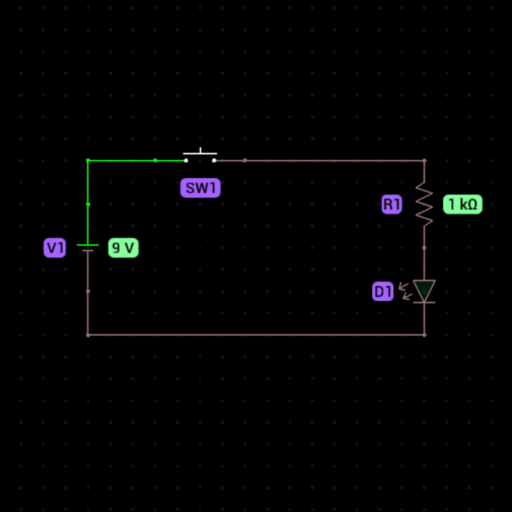
The LED lights up only when you press the push button switch. This simple circuit demonstrates how a push button can control current flow.

Components Needed:
- Green LED (1)
- Push Button Switch (1)
- 1kΩ Resistor (1)
- Battery (1)
- Breadboard (1)
- Jumper Wires
Step-by-Step Instructions:
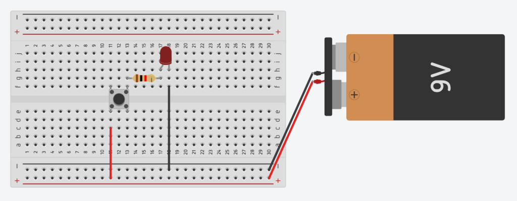
- Place the LED on the breadboard (long leg = anode, short leg = cathode).
- Connect one end of the 1kΩ resistor to the anode of the LED.
- Place the push button switch across the center gap of the breadboard.
- Connect the free end of the resistor to one terminal of the push button.
- Connect the positive terminal of the battery to the other terminal of the push button.
- Connect the cathode of the LED to the negative terminal of the battery.
- Press the button to light up the LED.

How It Works:
- When you press the button, it closes the circuit and allows current to flow from the battery, through the resistor, the LED, and back to the battery.
- The LED lights up because it gets the required current.
- When you release the button, the circuit opens, and the LED turns off.

Clear, precise and easy to understand diagrams. Thank you so much for this.
You’re most welcome, Daniel.
A GOOD THEORY AND GUIDELINES FOR A BASIC LED CIRCUIT WITH PUSHBUTTON SWITCH 🎓💡💡
We are glad that you found it useful, Samuel.