Back to: ELECTRONICS
In this project, we’ll set up a circuit using an RGB LED and 3 switches to control the red, green, and blue lights independently. Follow the steps below to build your circuit.
Components Needed:
- 1 RGB LED (Common Cathode or Common Anode)
- 3 Pushbutton switches
- 3 Resistors (220Ω or similar)
- Breadboard
- Jumper wires
- Power supply (5V)
Steps:
- Insert the RGB LED:
- Place the RGB LED in the center of your breadboard. An RGB LED has 4 pins:
- Cathode (negative) (if it’s a common cathode RGB LED) will go to the ground rail.
- The other 3 pins are for the Red, Green, and Blue colors. These will be connected to the switches and resistors.
- Place the RGB LED in the center of your breadboard. An RGB LED has 4 pins:
[image: gif of identifying the different legs]
- Connect the Cathode:
- Connect the cathode pin (common pin) of the RGB LED to the negative rail of the breadboard. This will be your ground connection.
- Attach Resistors:
- Place a 220Ω resistor into each row for the Red, Green, and Blue pins of the RGB LED. The resistors will limit the current flowing through the LED to prevent damage.
- Connect the other end of each resistor to a separate row that will be connected to the switches.

Photo credit: kitronik.co.uk
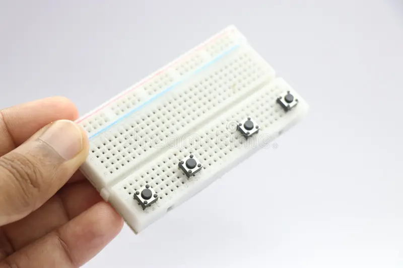
- Insert the Switches:
- Insert 3 pushbutton switches on the breadboard, one for each color (Red, Green, Blue). For each switch, make sure that when the switch is pressed, it will connect to the row where the resistor is connected.
- You can place the switches in a row with one pin for each color.

Photo credit: dreamstime
- Wiring the Switches:
- For each switch, connect one pin to the row with the resistor.
- The other pin of each switch will be connected to the positive rail (marked +) of the breadboard to provide power to the circuit when the switch is pressed.
[image: gif of these components placed on a breadboard]
- Testing the RGB LED:
- When you press a switch, it will send power to the corresponding color pin of the RGB LED, turning on that color.
- Pressing the Red switch will light up the red LED, pressing the Green switch will light up the green LED, and pressing the Blue switch will light up the blue LED.
- Connecting the Power Supply:
- Finally, connect the positive rail to your power supply (5V) and the negative rail to the ground (GND) of the power supply.
[image: gif of working circuit]
How It Works:
- Red: When the Red switch is pressed, current flows through the resistor to the Red pin of the RGB LED, lighting up the red color.
- Green: When the Green switch is pressed, current flows to the Green pin, lighting up the green color.
- Blue: When the Blue switch is pressed, current flows to the Blue pin, lighting up the blue color.
With this setup, each switch controls the color of the RGB LED. Pressing one switch at a time will light up one color, but you can combine presses to mix the colors and create different effects!
Conclusion:
Now, you have an RGB LED controlled by 3 switches, each switching on one of the three colors. With this simple circuit, you can experiment with different combinations of colors and learn how RGB LEDs work!
