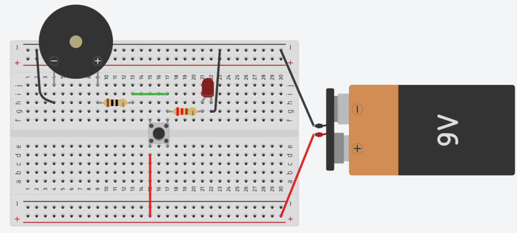
What It Does:
This simple circuit produces a buzzing sound while an LED lights up as an indicator. The buzzer and LED work together to alert you visually and audibly.

Components Needed:
- Buzzer (1)
- LED (1)
- Push button switch
- 10Ω Resistor (1)
- 220Ω Resistor (1)
- Battery (1)
- Breadboard (1)
- Jumper Wires
Step-by-Step Instructions:
- Insert the LED:
Place the LED on the breadboard. Connect the short leg (cathode) of the LED to the negative rail of the breadboard. - Connect the 220Ω Resistor:
Attach one end of the 220Ω resistor to the long leg (anode) of the LED. Leave the other end free for now. - Place the Buzzer:
Insert the buzzer onto the breadboard. Connect its positive terminal to the positive rail and its negative terminal to an empty row on the breadboard. - Connect the 10Ω Resistor:
Attach one end of the 10Ω resistor to the negative terminal of the buzzer. Leave the other end free for now. - Install the Pushbutton Switch:
Place the pushbutton switch on the breadboard, ensuring each side of the switch is on a separate row. - Wire the Resistors to the Pushbutton:
Connect the free end of the 220Ω resistor (from the LED) and the free end of the 10Ω resistor (from the buzzer) to the same side of the pushbutton switch. - Connect the Pushbutton to the Power Rail:
Use a jumper wire to connect the opposite side of the pushbutton to the positive rail of the breadboard. - Power the Circuit:
Connect the positive terminal of the battery to the positive rail and the negative terminal of the battery to the negative rail of the breadboard. - Test the Circuit:
Press the pushbutton. The LED will light up, and the buzzer will sound simultaneously.

How It Works:
- The battery supplies power to both the buzzer and the LED.
- The 220Ω resistor limits the current through the LED, protecting it from burning out.
- The 10Ω resistor reduces current through the buzzer, ensuring safe operation.
- When the circuit is complete, the buzzer produces a sound, and the LED lights up, providing both an audio and visual alert.
