What it Does
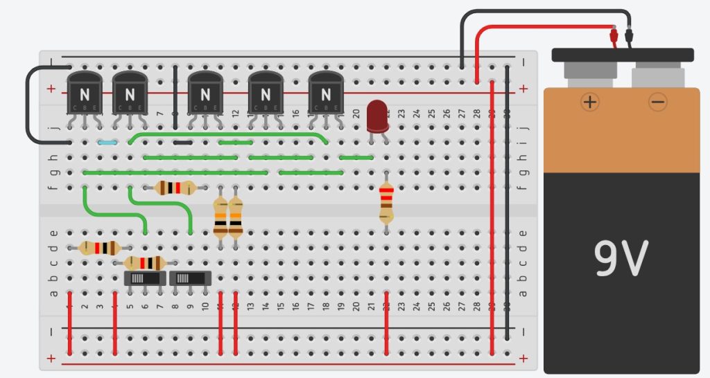
This circuit demonstrates the function of an XOR gate, which outputs HIGH (turns on the LED) when either of the two inputs is HIGH but not both. The LED only lights up when one push-button switch is pressed, and it stays off when both or neither are pressed.
Components Needed
- NPN transistors (BC547) – 5
- Resistors (220Ω) – 1
- Resistors (1kΩ) – 3
- Resistors (10kΩ) – 2
- Push-button switches – 2
- Green LED
- Breadboard
- Jumper wires
- Battery (9V) with clip
Connect the circuit using the diagram below

TinkerCAD circuit by jdardillac
How it Works
The XOR gate circuit works by combining the properties of AND, OR, and NOT gates. When neither switch is pressed (both inputs LOW), or when both are pressed (both inputs HIGH), the transistors either both remain OFF or both turn ON, preventing current from flowing through the LED, keeping it OFF. When only one of the switches is pressed, current flows through one transistor and the LED, lighting it up. The resistors limit the current to protect the transistors and the LED.
