What it Does
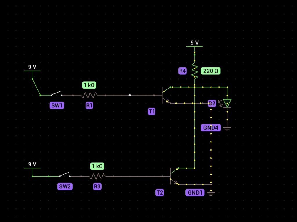
This circuit demonstrates the function of a NOR gate, which outputs LOW (turns off the LED) when either or both inputs (push-button switches) are HIGH. The LED only lights up when both switches are not pressed (inputs LOW).

Components Needed
- NPN transistors (BC547) – 2
- Resistor (220Ω) – 1
- Resistors (1kΩ) – 2
- Push-button switches – 2
- Green LED
- Breadboard
- Jumper wires
- Battery (9V) with clip
Step-by-Step Instructions
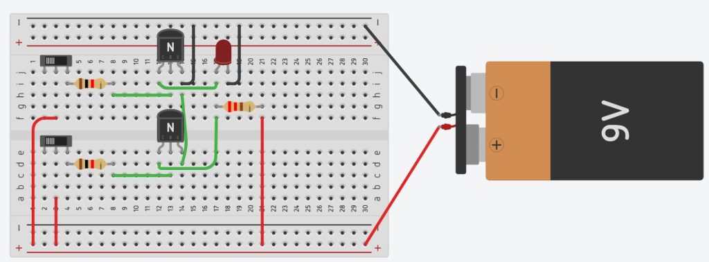
- Connect the 9V battery to the breadboard using the battery clip.
- Create a positive (Vcc) and negative (GND) rail on the breadboard.
- Insert the first NPN transistor into the breadboard. Label its legs as collector, base, and emitter.
- Insert the second NPN transistor next to the first one.
- Connect the emitters of both transistors to the GND rail.
- Place a 220Ω resistor between the positive rail and the anode (longer leg) of the LED.
- Connect the anode (longer leg) of the LED to the collectors of both transistors using a jumper wire.
- Place a 1kΩ resistor between the base of the first transistor and one terminal of the first push-button switch.
- Connect the other terminal of the first push-button switch to the positive rail.
- Place another 1kΩ resistor between the base of the second transistor and one terminal of the second push-button switch.
- Connect the other terminal of the second push-button switch to the positive rail.
- Verify all connections, then test the circuit by pressing each switch individually and both together to observe the LED behavior.

How it Works
This circuit combines the NOT and OR logic. When neither push-button switch is pressed (both inputs LOW), no current flows to the bases of the transistors, so both transistors remain OFF. In this state, the current flows through the LED, lighting it up. When either or both switches are pressed (input HIGH), one or both transistors turn ON, allowing current to bypass the LED, turning it OFF. The resistors limit the current flow to protect the components.
