What It Does:
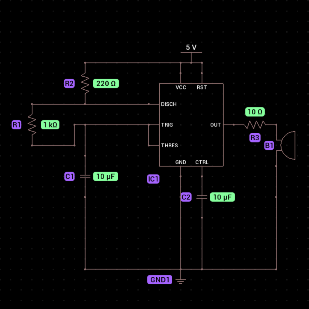
This circuit generates a simple buzzing sound using a 555 timer in astable mode. The 555 timer produces a continuous square wave signal, which drives a buzzer to create the sound.

Components Needed:
555 Timer IC (1)
- Buzzer (1)
- 1kΩ Resistor (1)
- 220Ω Resistor (1)
- 10Ω Resistor (1)
- 10µF Capacitor (2)
- Battery (1)
- Breadboard (1)
- Jumper Wires
Step-by-Step Instructions:
1. Place the 555 Timer IC on the Breadboard:
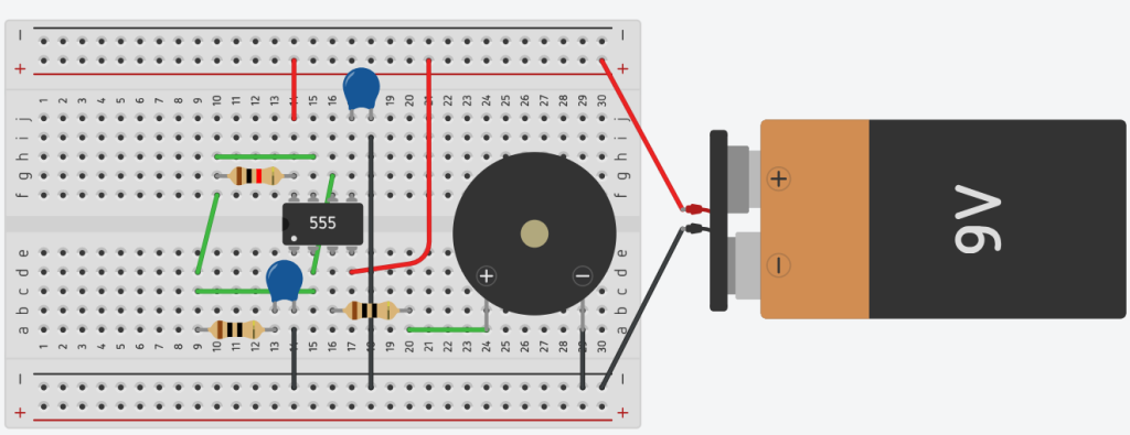
Insert the 555 timer IC into the breadboard, ensuring its pins straddle the center gap.
2. Connect Pin 1 (GND):
- Connect Pin 1 of the 555 timer to the negative rail of the breadboard.
3. Connect Pin 8 (VCC):
- Connect Pin 8 of the 555 timer to the positive rail of the breadboard.
4. Add the Buzzer:
- Connect the positive terminal of the buzzer to Pin 3 (output) of the 555 timer using a 10Ω resistor.
- Connect the negative terminal of the buzzer to the negative rail of the breadboard.
5. Connect the Timing Resistors and Capacitor:
- Place the 220Ω resistor between Pin 7 and Pin 8 (positive rail).
- Place the 1kΩ resistor between Pin 7 and Pin 6.
- Place the 10µF capacitor between Pin 2 and Pin 1. Ensure the longer leg (positive) of the capacitor connects to Pin 2.
- Place the second 1010µF on pin 5 and connect the other leg to ground using a jumper wire.
6. Wire Pin 2 and Pin 6:
- Connect Pin 2 to Pin 6 using a jumper wire.
7. Connect Pin 4 (Reset):
- Connect Pin 4 to Pin 8 (VCC) to disable the reset function.
8. Power the Circuit:
- Connect the positive terminal of the battery to the positive rail of the breadboard.
- Connect the negative terminal of the battery to the negative rail of the breadboard.
9. Test the Circuit:
- When powered, the buzzer will produce a steady buzzing sound.

How It Works:
- The 555 timer operates in astable mode, generating a continuous square wave signal.
- The frequency of the signal is determined by the 10kΩ resistor, 470kΩ resistor, and 10µF capacitor.
- This signal drives the buzzer, causing it to vibrate and produce sound.
- The pitch of the sound can be adjusted by changing the values of the resistors or capacitor, which alters the frequency of the oscillation.
