What it does:
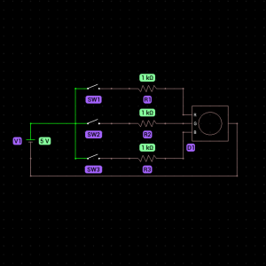
This RGB LED circuit lights up the red, green, or blue component of an RGB LED when you press the corresponding pushbutton switch. This setup demonstrates how multiple switches can control different parts of a circuit independently.

Components Needed:
- RGB LED (1)
- Push Button Switch (3)
- 1kΩ Resistor (3)
- Battery (1)
- Battery Clip (1)
- Breadboard (1)
- Jumper Wires
Step-by-Step Instructions:
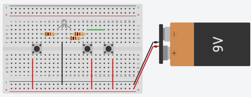
- Place the RGB LED on the Breadboard:
- Identify the pins of the RGB LED: the longest pin is the common cathode (negative), and the others are for red, green, and blue.
- Insert the LED into the breadboard so that the pins are separate and accessible.
- Connect the Common Cathode:
- Attach a jumper wire to the longest pin (common cathode) of the RGB LED and connect it to the negative rail of the breadboard.
- Add Resistors to Each Color Pin:
- Connect one 1kΩ resistor to each of the red, green, and blue pins of the RGB LED.
- Place the Push Button Switches:
- Place three pushbutton switches across the center gap of the breadboard. Ensure they are spaced apart for easy access.
- Connect Resistors to Push Buttons:
- Connect the free end of the resistor attached to the red pin to one terminal of the first push button.
- Repeat the process for the green and blue resistors, connecting them to the first terminals of the second and third push buttons, respectively.
- Wire the Push Buttons to the Battery’s Positive Terminal:
- Use jumper wires to connect the second terminal of each push button to the positive rail of the breadboard.
- Power the Circuit:
- Connect the positive terminal of the battery to the positive rail of the breadboard using a battery clip and a jumper wire.
- Connect the negative terminal of the battery to the negative rail of the breadboard.
- Test the Circuit:
- Press each pushbutton one at a time. The RGB LED should light up in red, green, or blue, depending on which button you press.

How It Works:
- Each pushbutton acts as a switch for the current flow to its respective color pin on the RGB LED.
- When you press a button, it closes the circuit for that color, allowing current to flow from the battery, through the resistor and LED, and back to the battery.
- The resistor limits the current to prevent damage to the LED.
- Releasing the button opens the circuit, turning off the corresponding LED color.
